
AA334 Chassis Preparation
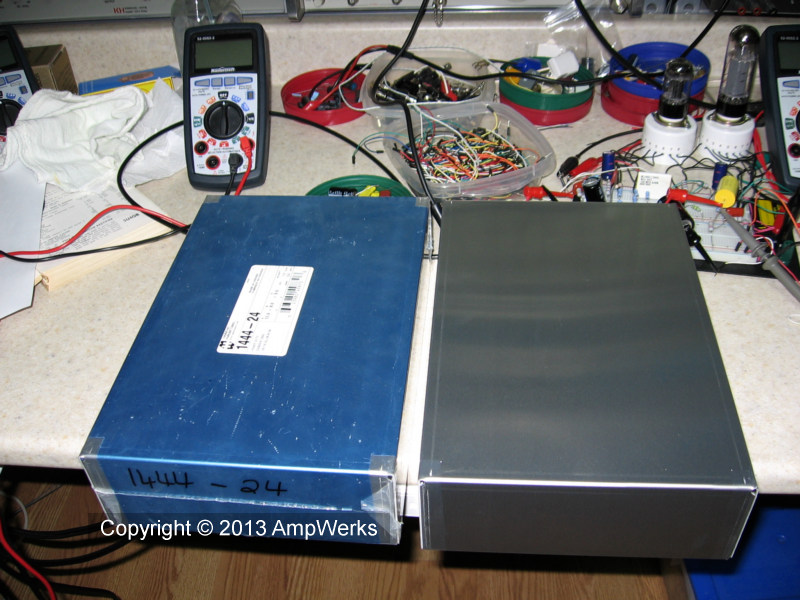
I started with a pair of blank Hammond 1444-24 chassis and bottom panels. Each chassis measures 8 x 12 x 3 inches and is aluminum with a natural finish.
I created machining templates in Corel Draw for the front, top, back, and bottom panels. The templates are drawn to scale and act as guides for drilling and punching. The templates were printed on removable label stock and applied directly to the chassis panels.
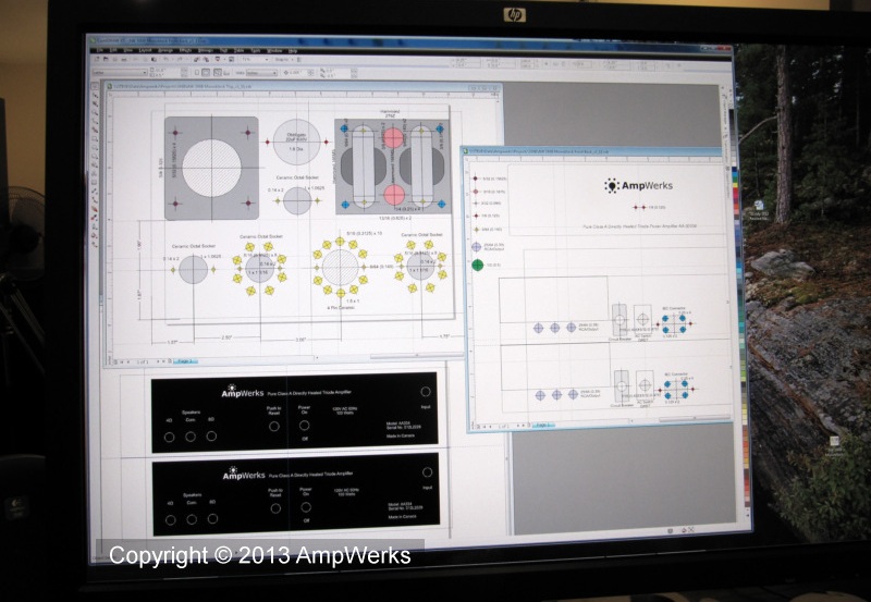
I positioned the power transformer and output transformer near the back of the chassis. The large filter capacitor and the 6NO45 Amperite delay relay sit between the transformers. All the tubes are at the front.
Looking at the chassis from the front, the 6SL7 preamp tube is on the left with the EL34 driver tube next to it. The third tube is the 300B output tube, and the fourth tube is the 5U4GB rectifier
This layout keeps the preamp tube as far away as possible from the rectifier and power transformer. Although the output transformer is relatively close to the 6SL7, the transformer is well shielded and scope tests found no trace of any feedback issues.
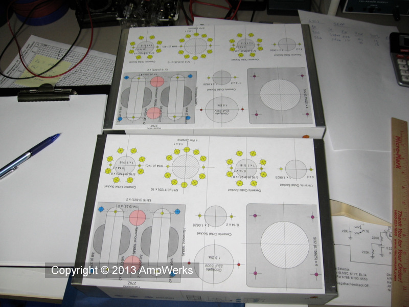
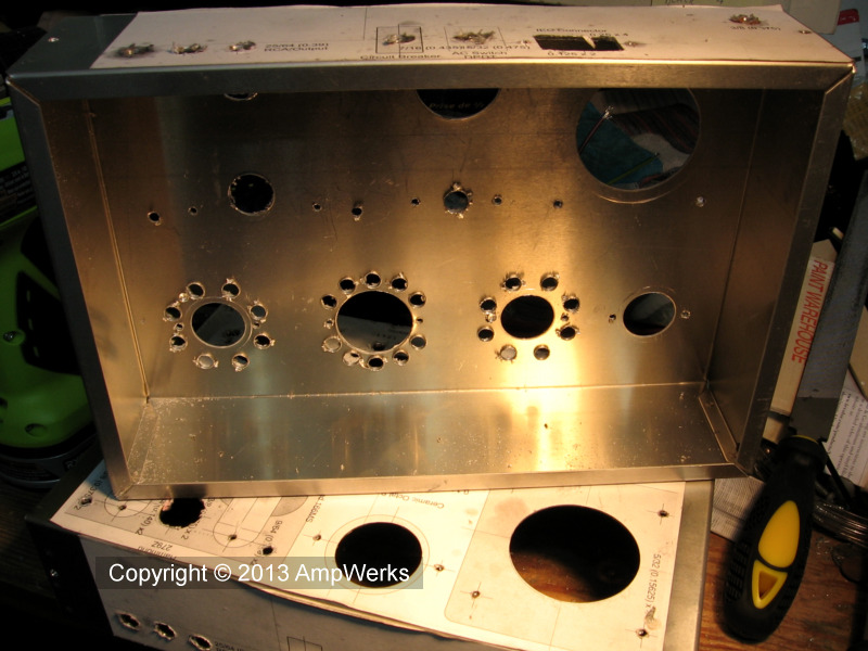
This is what the chassis looked like with the templates applied. After marking the centre of every hole with a centre punch, I proceeded to drill, punch and file as required.
This is where our hands get dirty!
The templates help protect the surface of the chassis during the various machining operations. I don't have any fancy CNC machinery yet, just a drill press and some basic hand tools, so this is not my favourite part of the project.
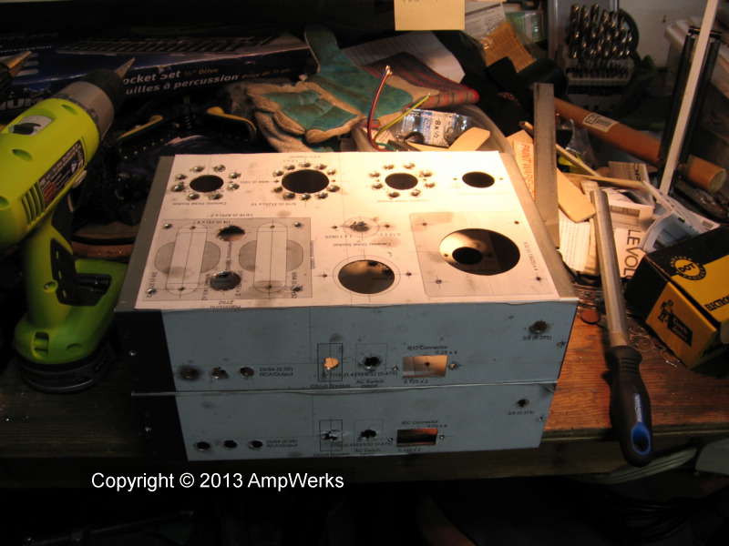
Most of the holes are round so I drillled them or punched them using Greenlee chassis punches of various sizes, but the rectangular hole for the IEC power cord connector on the back panel had to be made the hard way – drill and file.
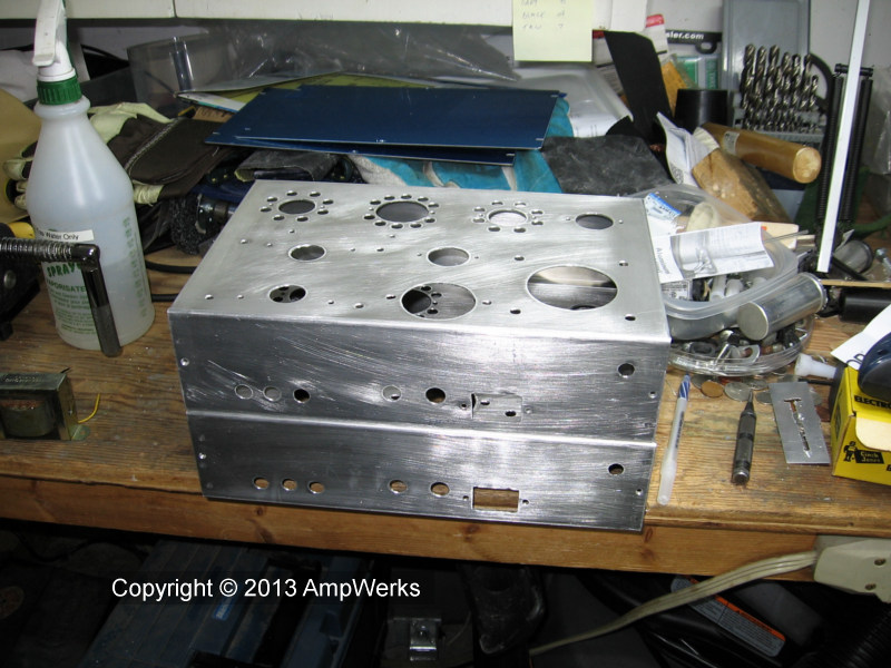
Every hole had to be deburred by hand, inside and out.
After drilling, punching and deburring I peeled the templates off and then wet sanded the two chassis. Next was degrease, primer, and up to four coats of black textured lacquer. Pictured below are the two chassis ready for primer.
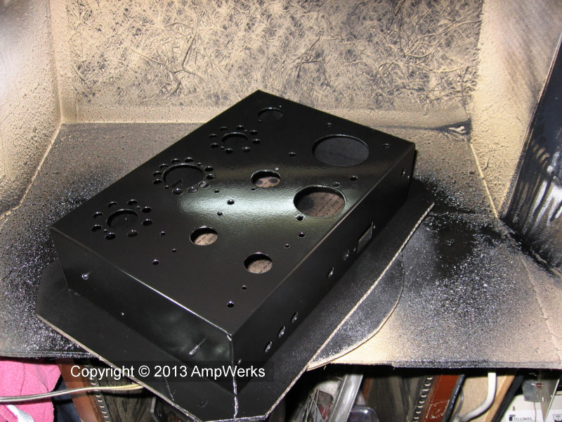
My paint finishing processes are the result of a great deal of trial and error and experimentation. I can now achieve consistent, high quality finishes with a level of durability approaching that of powder coating.
Bottom panels with screens attached, ready for the final finishing steps.
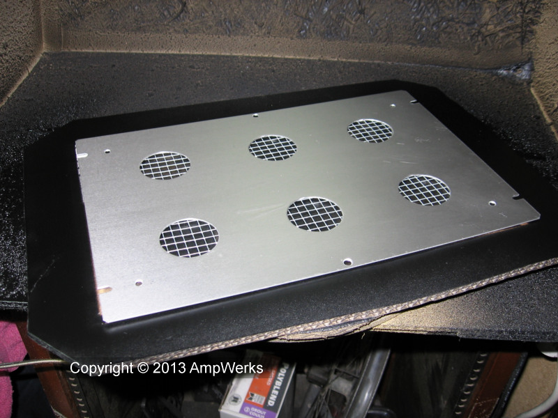
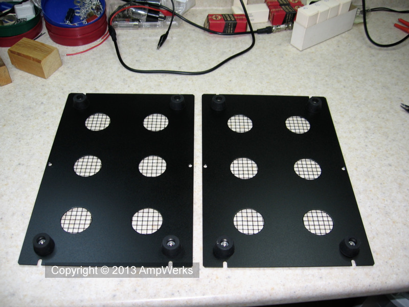
Here are the painted bottom panels with the screens and rubber feet installed.
I dismantled the power transformers and applied a low lustre satin black lacquer finish to them, as well as to the large Obbligato filter capacitors which will be mounted on top of the chassis.