AmpWerks AA334 Assembly and Wiring
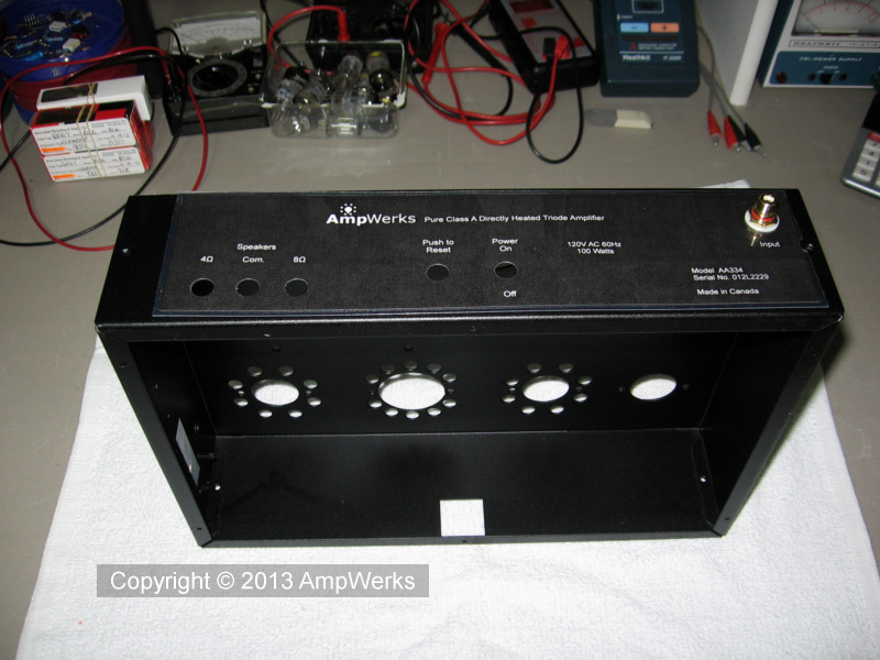
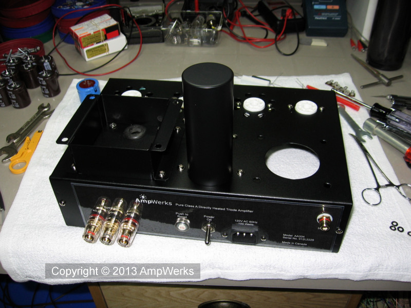
The back panel labels were prepared in Corel Draw and then printed and laminated. The labels are held in place by the switches and binding posts.
The speaker terminals are on 3/4 in. centres to accommodate standard dual banana plugs commonly used for speaker connections.
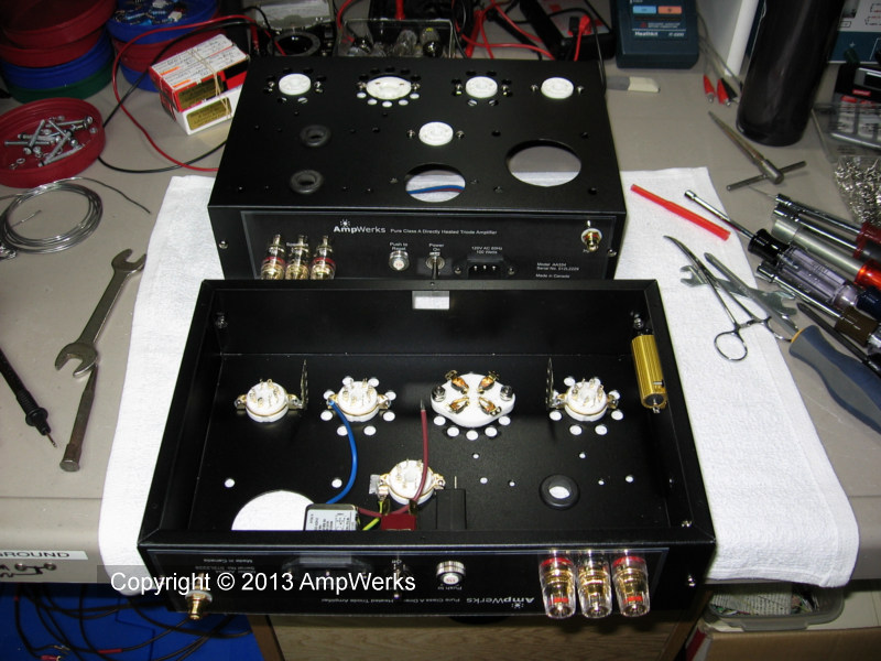
Tube sockets are next. I used ceramic sockets with gold plated pins for all of the tubes. The 4-pin sockets for the 300B output tubes are shock mounted with rubber o-rings. 300Bs can be somewhat microphonic.
The 50 Watt aluminum resistor is mounted on the inside of the chassis and uses it for a heat sink. I mounted a 2 in. by 6 in. piece of 0.06 in. thick scrap aluminum between the resistor and the chassis to spread the heat and prevent a hot spot. It works well. The entire side of the amp becomes only slightly warm after extended use. This resistor connects the cathode of the 300B tube to circuit ground and generates the 74 V negative bias for the grid.
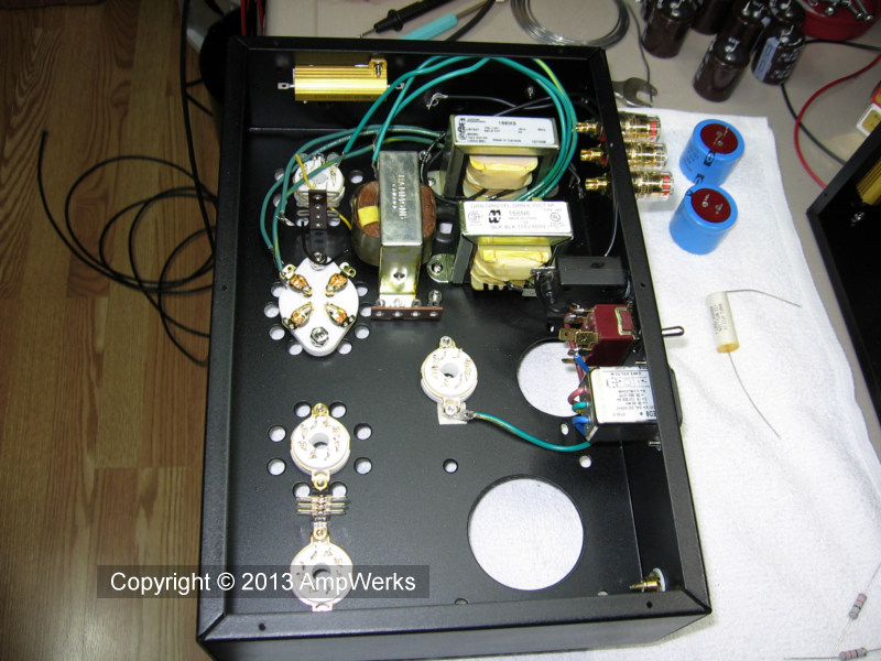
Next I mounted some of the major components inside the chassis. I should have installed the large Obbligato filter capacitor before I mounted the power switch since the capacitor has to be inserted from the underside of the chassis. Duh. Hey, after 40 years it takes a while to get back up to speed!
Note that the AC line ground (short green wire) is connected to the chassis at the 6NO45 socket. This ensures that the chassis and all of the amplifier's external metal components are grounded for safety.
The amplifier's circuit ground is isloated from the chassis to prevent ground loops which can cause hum. The audio system's circuit ground will be connected to the power line ground at only one point, most likely at the preamp.
The 1.5 Amp circuit breaker on the back panel is a necessary safety feature. A fuse would do just as well.
Now we are ready to mount some serious iron...
There, that looks better.
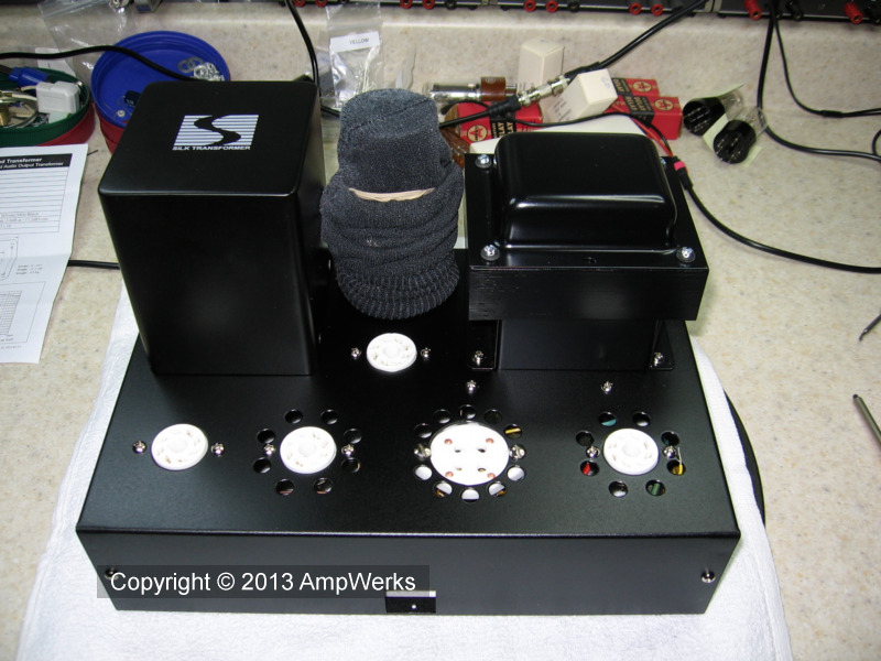
The old sock on the big filter cap is there to prevent scratching the fresh paint.
Class A amplifiers are sensitive to power supply ripple. The AA334's beefy supply provides ripple-free power under full load conditions due to its multiple filter stages and energy storage capabilities.
The electrolytic filter capacitors are mounted inside the chassis. The main leg of the ground bus is visible above the tube sockets.
The power transformer's Z mounting bracket raises the entire transformer above the chassis. This leaves room to mount the smaller filament and bucking transformers directly beneath it under the chassis. The third Hammond inductor mounted at 90º to the other two is the filter choke.
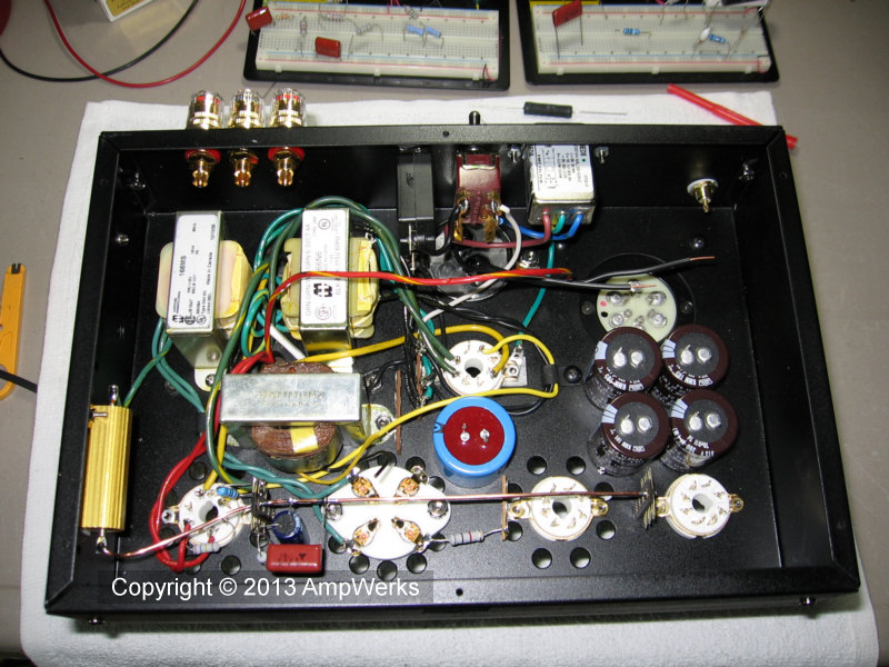
All of the resistors except the big wirewound are 2 Watt metal film. Metal film resistors are stable and are low noise. Coupling capacitors are Obbligato Gold Premium and Cornell Dubilier. There are only 3 capacitors in the signal path, but I'm going to remove the input capacitor because my line level signals have no DC component.
We used existing component leads where possible and teflon insulated hookup wire where required. The ground bus is 14 ga. bare solid copper wire.
The wiring is almost complete in the photo below. Still to come are the polypropylene bypass capacitors and the neon pilot lights.
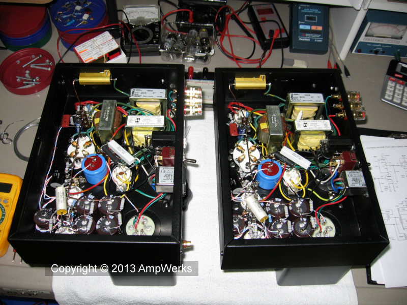
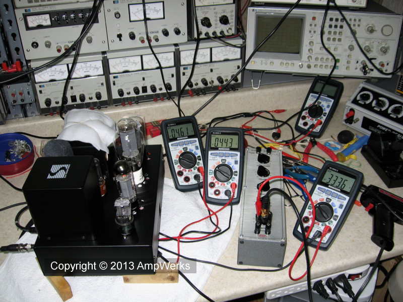
The big moment arrives — first time power up!
No smoke, no flames. Voltages look good. All is well! Break out the champagne.
The amp is up on blocks to keep it vertical while accommodating the meter leads that connect to test points beneath the chassis. The decade resistance box indicates that I was tweaking something at the time. I think it was the B+ dropping resistor for the input stage.
The 300B, 5U4 and most directly heated (DH) tubes are designed to operate base down, or in a specified safe orientation. The filament expands when hot to the point where it can droop and touch other internal tube elements if the tube is not in a safe position. According to the tube manual each of our DH tubes does have a safe horizontal orientation, but with our chassis layout they are at odds, so to be safe I keep the amps upright when powered up.